Some Effects of Local Corrosion
A common issue that I see in my role as a structural engineer is corrosion (and lots of it!). After finding some corrosion, I’m often asked: “how much strength has been lost”?
Sometimes the answer is obvious:
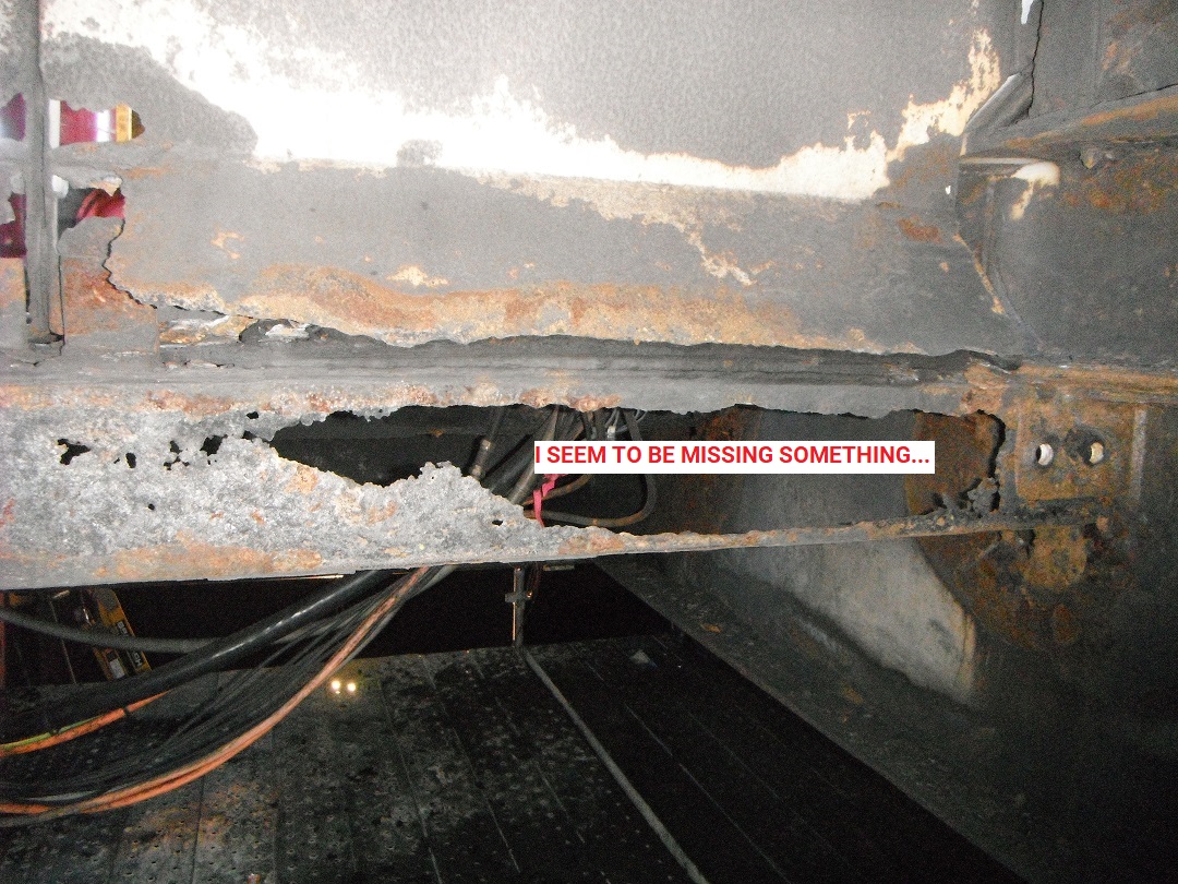
But often it’s a bit trickier, especially when small pits are located on large surfaces.
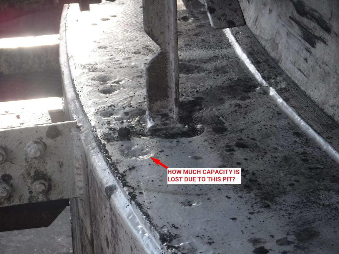
Since the potential ranges of pit size & location is effectively infinite, and there is a need to consider deflection, fatigue and ultimate limit states, it’s usually not possible to give an easy answer. The gold standard for determining the effects of corrosion is a Finite Element Analysis (FEA). However, this takes time and is not something that can be done rapidly on site. Therefore I thought I’d do some test models and trial some other potential methods for determining stress caused by corrosion.
Ultimate Behaviour
For ultimate behaviour in tension it is usually assumed that the whole section can achieve the full yield strength of the steel. Local stress concentrations, eccentric moments etc. do not matter - as the section goes plastic these stresses will redistribute (provided the section doesn’t fracture first).
For compression loads though, buckling may occur and significantly reduce strength. Rather than occurring uniformly along the plate, yielding concentrates in a “plastic hinge” in the buckled zone. This is heavily dependent on plate thickness.
Behaviour in Service
When considering fatigue (I’m ignoring deflection as it doesn’t usually affect my work), any stress concentrations are very important. Fatigue life is proportional to \(\sigma^{3}\), and a 25% increase in stress halves fatigue life. Therefore the size of the corroded area, the depth of corrosion and the location (in both width & thickness) are all important.
To try and identify a simple approach that could be used to quickly determine the effects of corrosion, I brainstormed a number of possible ideas. The following seemed reasonable to me at first:
-
Simply determine how much of the cross-section has been lost, and use that to determine the increase in strength.
\[\sigma_{\text{corroded}} = \sigma_{\text{original}} \frac{A_{\text{original}}}{A_{\text{corroded}}}\]This has the advantages that it is very simple to calculate. However, this method ignores local effects of stress concentration and eccentricity.
-
If the area of corrosion is small enough, it may not have much effect on the overall strength of the section. However, local stresses in the corroded area could be higher. Therefore, the stress in the corroded section might be approximated by:
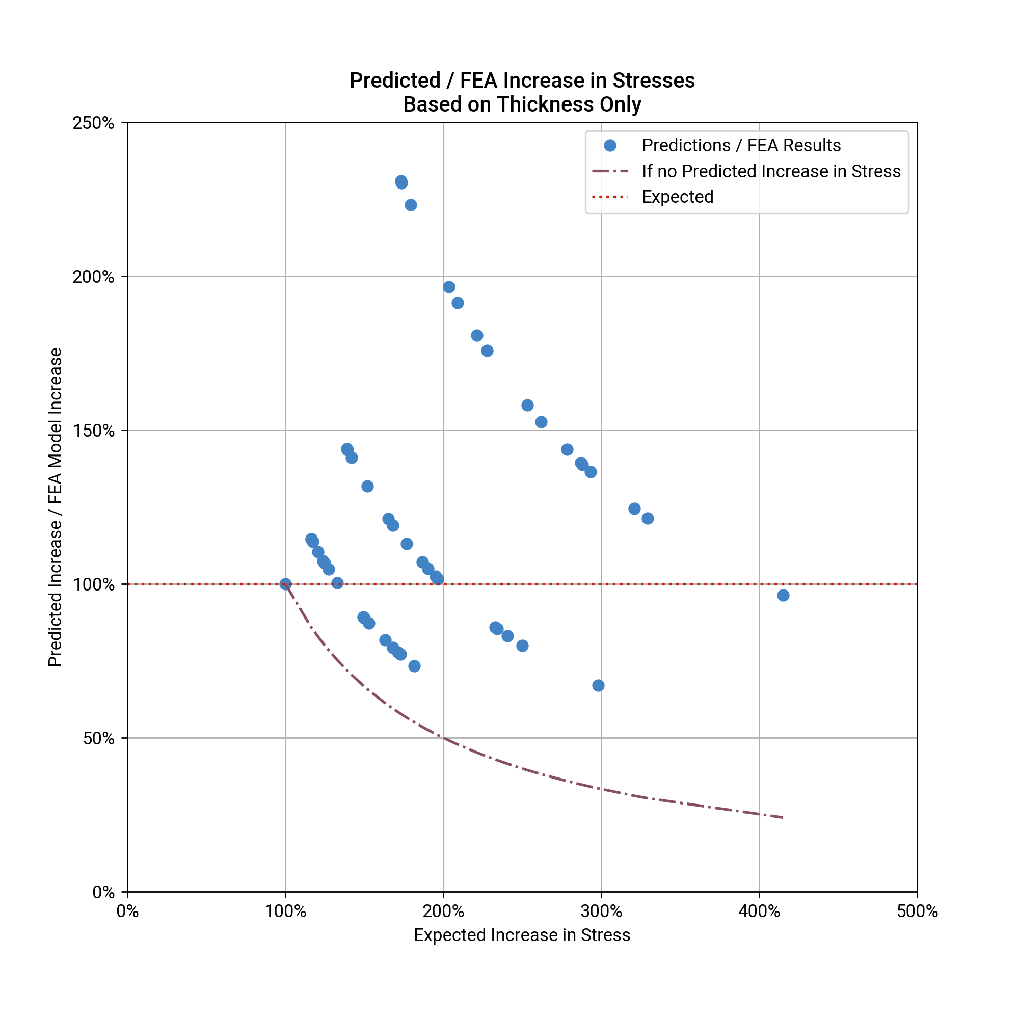
\[\sigma_{\text{corroded}} = \sigma_{\text{original}} \frac{t_{\text{original}}}{t_{\text{corroded}}}\]Again however, this method ignores the local effects of stress concentration and eccentricity.
-
This approach could be extended to consider the local effects of section loss & eccentricity caused by the corrosion:
-
Calculate the increase in stress caused by the loss of area, and;
-
Add the additional stress caused by any eccentricity of the section loss, approximately:
Where stresses are less than yield (elastic), this can be calculated as:
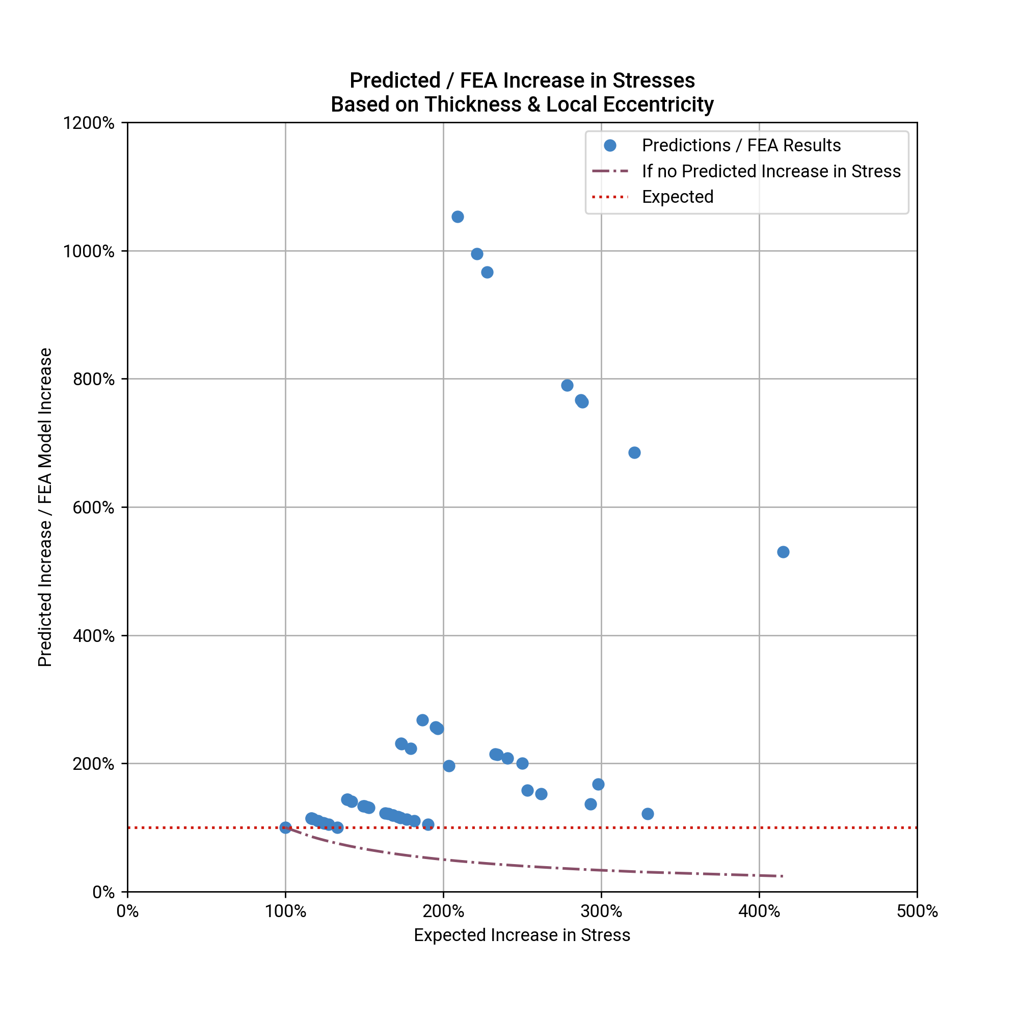
\[\sigma_{\text{corroded}} = \sigma_{ \text{original}} \left( \frac{t_{\text{original}}}{t_{\text{corroded}}} + \frac {6 \cdot k \cdot t_{\text{original}} \cdot \text{eccentricity}}{ t_{\text{corroded}}^2} \right)\]This approach begins to think about the effects of eccentricity on the stresses, but:
-
If the structure is statically indeterminate, the stresses depend on the relative stiffness of each component. This is described by the variable \(k\) in the equation above. \(k\) could range between 1, if all the moments due to eccentricity are in the corroded area, and 0, if they are all in un-corroded steel. The value of \(k\) is likely to be very difficult to determine absent an FEA model.
-
Again, it ignores stress concentration effects due to the shape of the corroded area.
-
-
Some sort of approximation to a simple beam could be made. However where corrosion areas are irregular it would likely be difficult to do this quickly.
-
The gold standard would be to do an FEA model. This will account for the local effects of the section loss, eccentricity of corroded area and any stress concentration effects due to the shape of the corroded area. It will also account for any global effects on the behaviour of the whole member caused by the corrosion.
Test Models
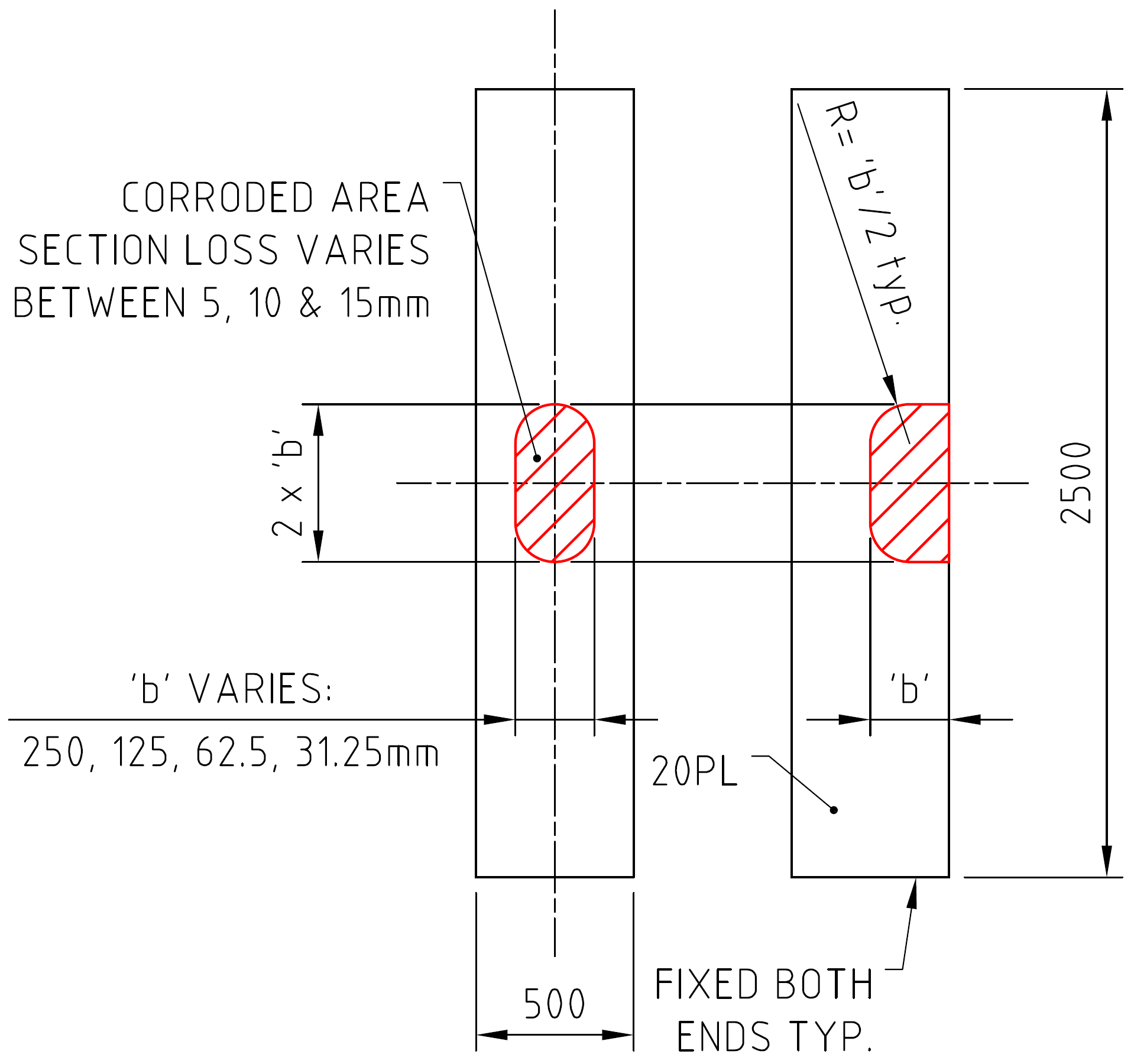
To test out some of these approaches, I decided to put together a series of test FEA models, using the following patch of corrosion:
To look at ultimate load effects a non-linear material analysis was used, assuming the steel was elastic-perfectly plastic. The following figure shows the ultimate tension capacity test:
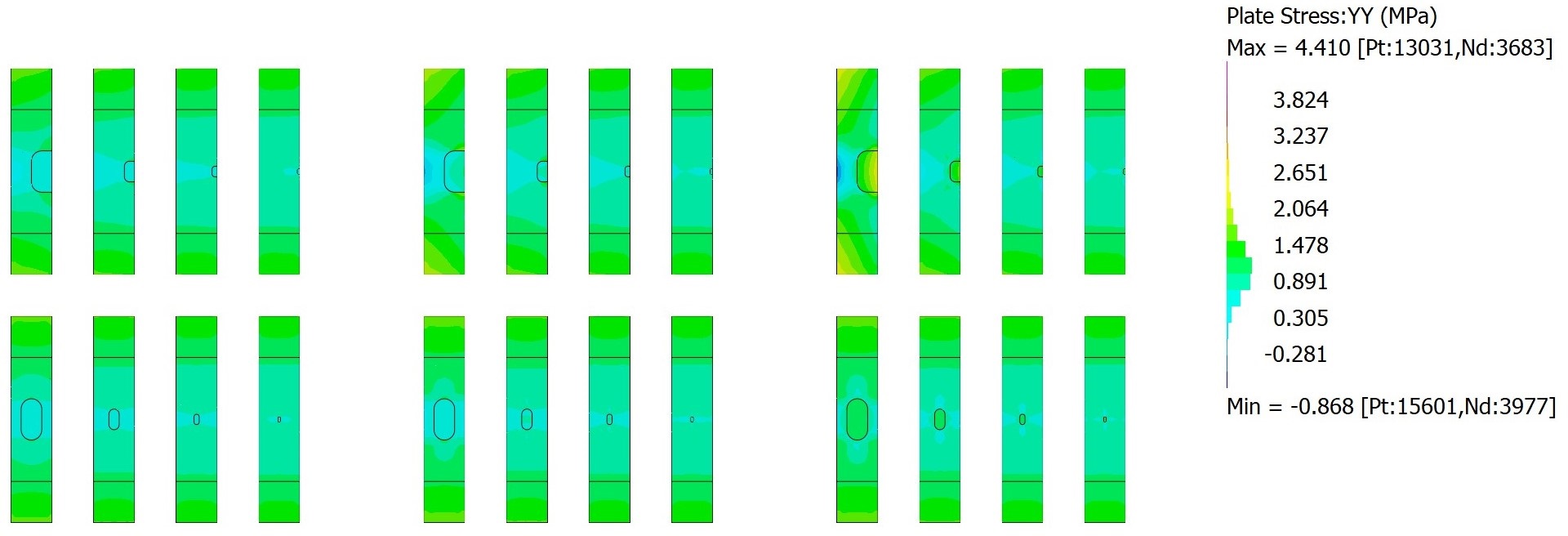
For stresses below ultimate, a linear-static analysis was carried out with a constant unit stress (1MPa) applied.
So What Did I Learn (If Anything?)
Ultimate Behaviour
Ultimate behaviour of the corroded plates was basically as expected. In tension, the capacity depended entirely on the total section loss that occurred. All configurations analysed failed at a load determined only by the remaining area of steel. The following figure shows typical load-deflection curves:
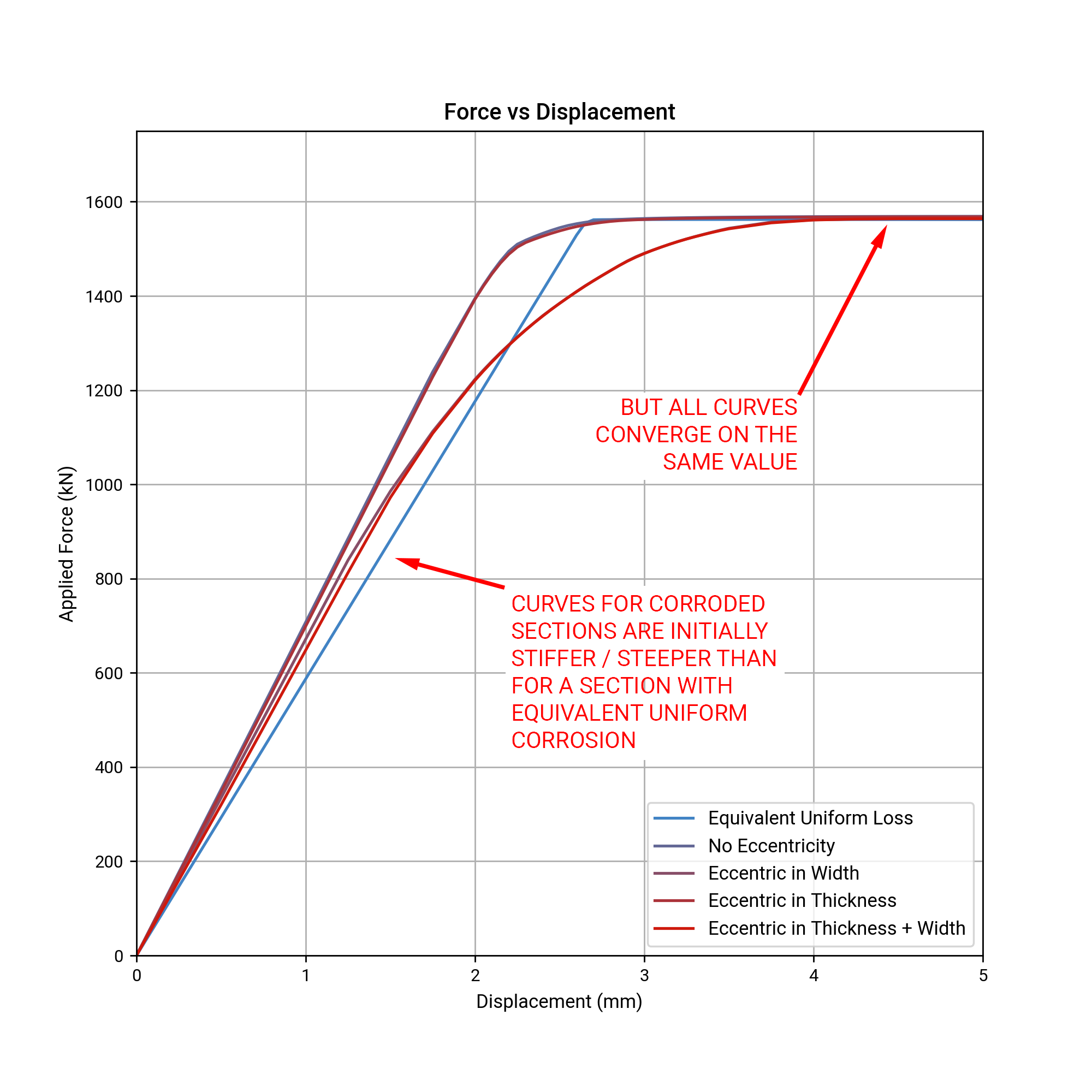
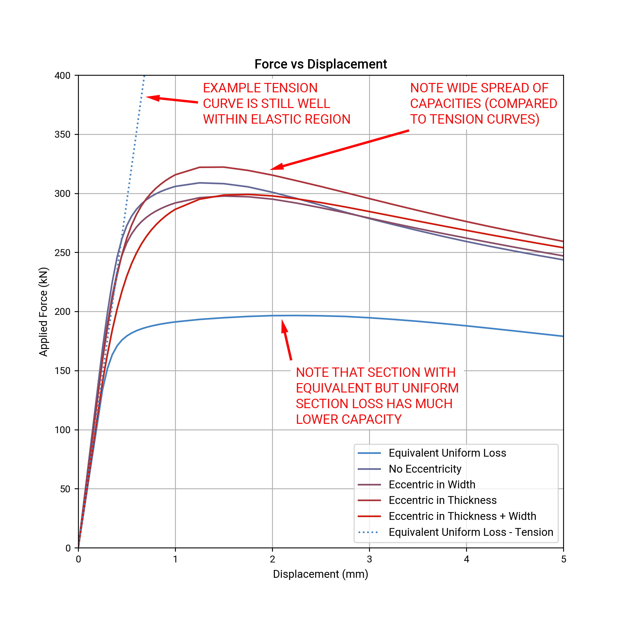
In compression there was a very wide spread of failure loads. Again, this was as expected, as compressive buckling is heavily dependent on thickness and secondary moments caused by eccentricity. In all cases, an equivalent uniform section loss gave a lower buckling resistance than the actual corroded models. Again, this was as expected because it concentrated the material closer to the centreline (where it has less ability to resist buckling) than in the corroded models (where the intact steel was distributed further away from the centreline). The following figure shows some sample load-deflection curves:
Behaviour in Service
In contrast to ultimate behaviour, none of my approaches for determining stresses in the elastic range were accurate, even for preliminary site assessments. I was expecting them to be inaccurate, but I was astounded by just how inaccurate!
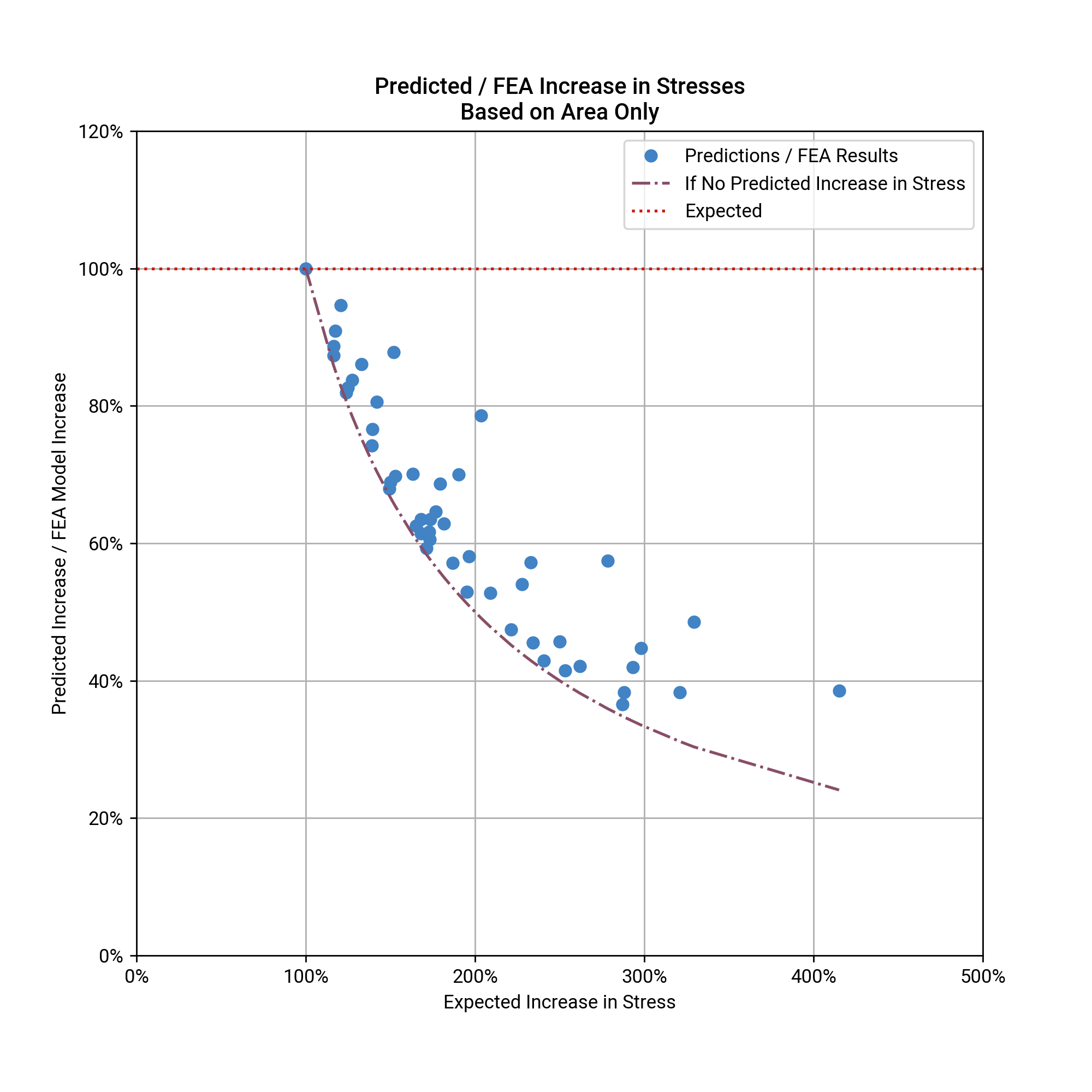
Using the reduction in area badly underestimates the increase in stress:
Using the reduction in thickness isn’t any better, only it overestimates the increase in stresses:
And trying to account for the local eccentricity in thickness overestimates things even more:
So far all these approaches have ignored the eccentricity in width of the corrosion. Because I didn’t want to spend more time thinking about equations, I pulled out Python’s scikit-learn module. After adding some terms for eccentricity in width I performed multi-variable linear regression (scikit-learn may have been overkill). Adding in some terms for the the eccentricity in width resulted in significantly better estimates:
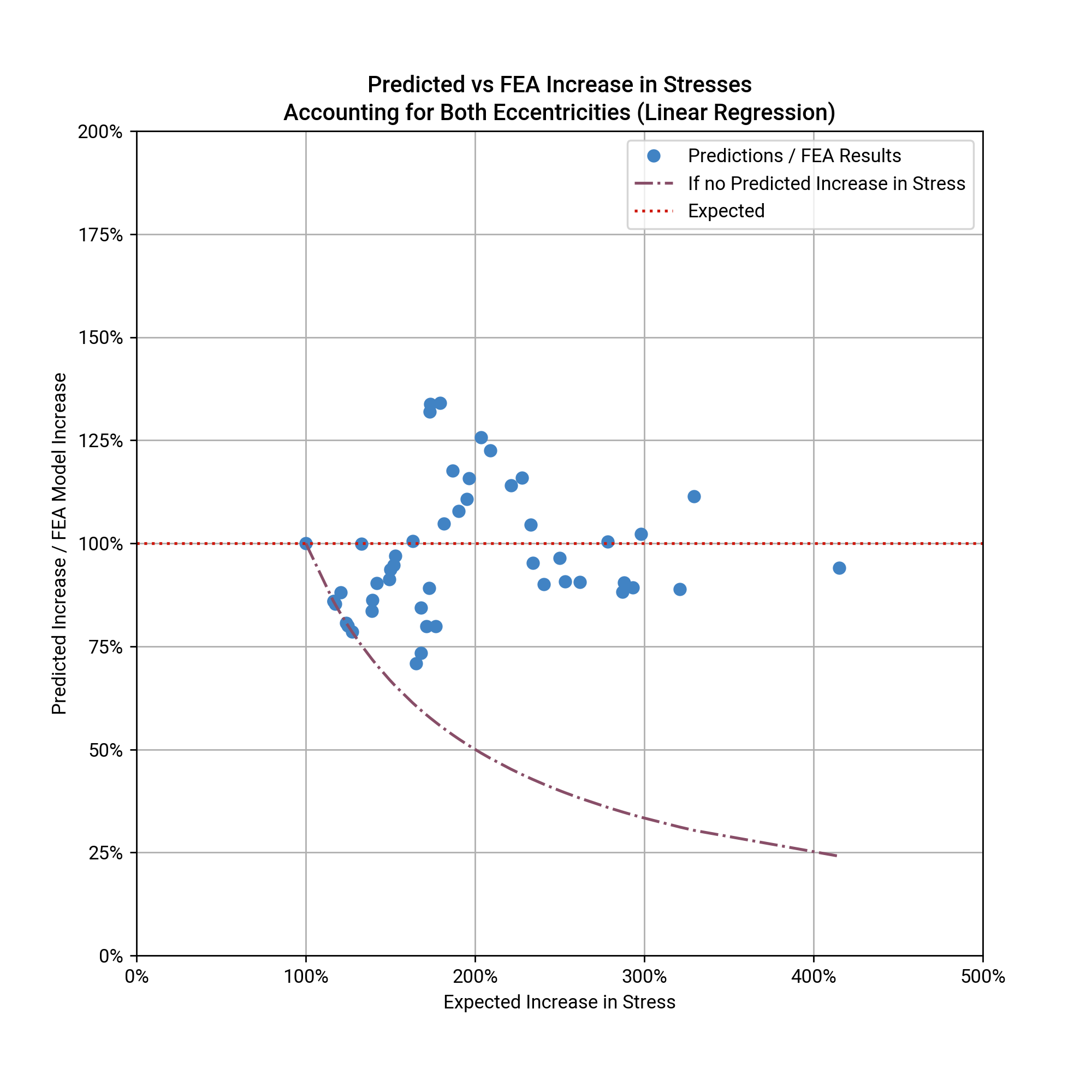
However, peak errors were over 25% - not really accurate enough if you’re concerned about fatigue (although perhaps accurate enough for other purposes). Also, I wouldn’t want to trust the resulting equation based on the small number of scenarios I considered - I can think of a number of other variables I haven’t considered that could affect the resulting stresses.
Why The Inaccuracies?
So why were my initial ideas for quickly determining the stresses wrong? And what else needs to be considered? A few things come to mind.
-
Probably most counter-intuitive was that all the methods above assume the peak stress is in the corroded plate. The peak stress is often in the surrounding plate, and the simple methods above don’t address this at all. The most likely explanation for this is stress re-distribution between the corroded and un-corroded areas.
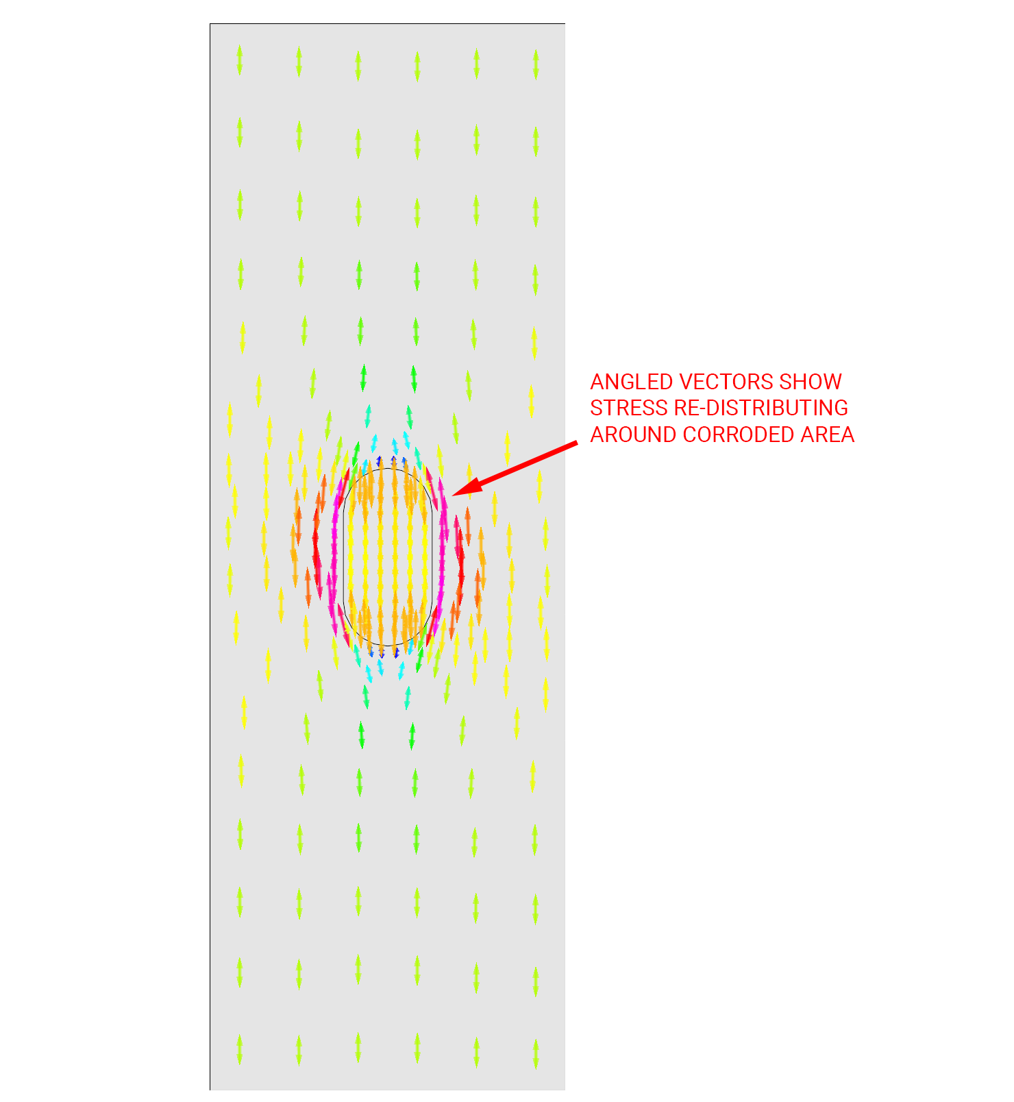
Note that the re-distribution of stresses around the corroded area also results in secondary stresses perpendicular to the main stress field.
-
Another observation was that the approximation using area tended to underestimate and the approximation using thickness tended to overestimate the increase in stresses. The method using area underestimates the increase in stress, because it assumes that stress is fully redistributed across the plate. The method using thickness overestimates the stress for the opposite reason - it doesn’t allow for any re-distribution of stress across the plate at all. In reality, stresses do re-distribute, being attracted to the thicker, and therefore stiffer, sections of the plate. The results are a peak stress somewhere between the 2x methods.
-
Method 3, which adds eccentricity to the thickness only approximation, is particularly inaccurate because it turns out that moments caused by the eccentricity in thickness are not taken by the corroded region. Using linear regression, the parameter \(k\) which distributes the moment between the corroded plate and the surrounding plate was found to be 0. Effectively all of the moment due to eccentricity in thickness is taken by the surrounding un-corroded steel, and the corroded section acts as a membrane carrying axial forces only.
-
There are a number of other variables that I can think of that may have affected these results. These include the shape of the corroded area such as length-to-width ratio, corner radius and irregularities. The through thickness profile may also have an effect, as corrosion is rarely as uniform as the test models above. Sharp notches at the bottom of corroded areas could cause very high stress concentrations locally.
Final Thoughts
The results above can be summarised as follows:
-
If you’re interested in ultimate behaviour of corroded steel, the total area lost is probably the most important thing, at least in tension. In compression, buckling is also important but again, simply treating the section loss as uniform is generally good enough.
-
Below ultimate loads though, there doesn’t seem to be any simple way of determining the section loss. You’re much better off telling your clients you don’t know and getting the time to do an FEA model.
If you do need a quick & dirty way of figuring out the potential effects of section loss, I’d go with the simple ratio of thicknesses method listed above. At least it seems like it should be conservative (often very conservative).
This was an interesting exercise to go through. It helped reinforce some things I already knew (about ultimate behaviour of corroded steel). However it also made me aware of areas where my assumptions were grossly wrong, including but not limited to:
-
That the highest stress is always in the corroded area, and;
-
That there would be moments in the corroded area caused by any eccentricity.
And it’s usually a good thing when you find out your assumptions are wrong, especially if its before something’s fallen down and killed someone.
P.S.
It’s been a while since my last post. Family, work and other things have intervened to delay this one. Hopefully the next one will be quicker to get out…