What They Didn't Teach Me at University - Stiffness
No university course can teach you everything about engineering, and mine wasn’t an exception. One of the things that I didn’t learn about at uni (or that I missed…) was the use and importance of stiffness in structural analysis. Since uni though, and especially in the last few years I have been gaining a greater appreciation of how useful it can be.
Springs, Lots of Springs
Anyone who has done high school physics probably saw the following equation:
\[F=kx\]This is Hooke’s Law, which describes the behaviour of a spring. \(F\) is the force the spring can exert, \(x\) is the displacement (the amount it is stretched/squashed) and \(k\) is the spring constant or it’s “stiffness”. In high school you probably only looked at springs that looked something like this:
 Image from Wikipedia, License: CC BY-SA 3.0
However any elastic object can be described by the same equation. This includes beams, columns, floor slabs and most of the structure in a normal building. This provides a very useful concept for understanding how structures behave: they are collections of large numbers of springs, all pushed & pulled by the loads applied and in turn pushing and pulling on each other.
The analogy does fall apart when loads get near the ultimate capacity of a structure, where yielding, buckling, fracture and other odd things can happen. For the purposes of most basic structural engineering though, the “bunch of springs” analogy works fine.
Thinking About Stiffness is Useful
So how can considering stiffness be useful?
Probably the first time I considered stiffness directly would have been for determining foundation loads. Except for statically determinate structures, reactions on the foundation (or other structures) depend on the interaction of the structure and the foundation. In my experience clients in my industry don’t want to pay for geotechnical investigations to determine the actual stiffness of the foundation. So I would look at the info for their nearest borehole (usually at least 100m+ away…), dig out my textbooks, choose between “silty clay” or “clayey silt” (?!?!?!?!) and make my best (wildly inaccurate) guess of the stiffness. I would then do a very conservative (and expensive) design. The client wouldn’t like it, pay for a geotechnical investigation and give it to a different consultant to redesign the footing. Their design would be cheaper because they had the right information to start with. And I would look like an idiot. True story (not that I’m bitter about it…). So let’s skip footings.
When the reaction is another structure however, usual practice is to just assume restraints are either perfectly fixed or perfectly pinned and to ignore their real stiffness. This often gives good enough results but sometimes using the correct stiffness is useful, or even required to make a design work.
A couple of years ago now I was involved in a 3rd party review of the deconstruction of a wharf structure, which provided a number of examples of just how important considering stiffness can be. To keep it short though I’ll focus on the deconstruction of a large conveyor truss.
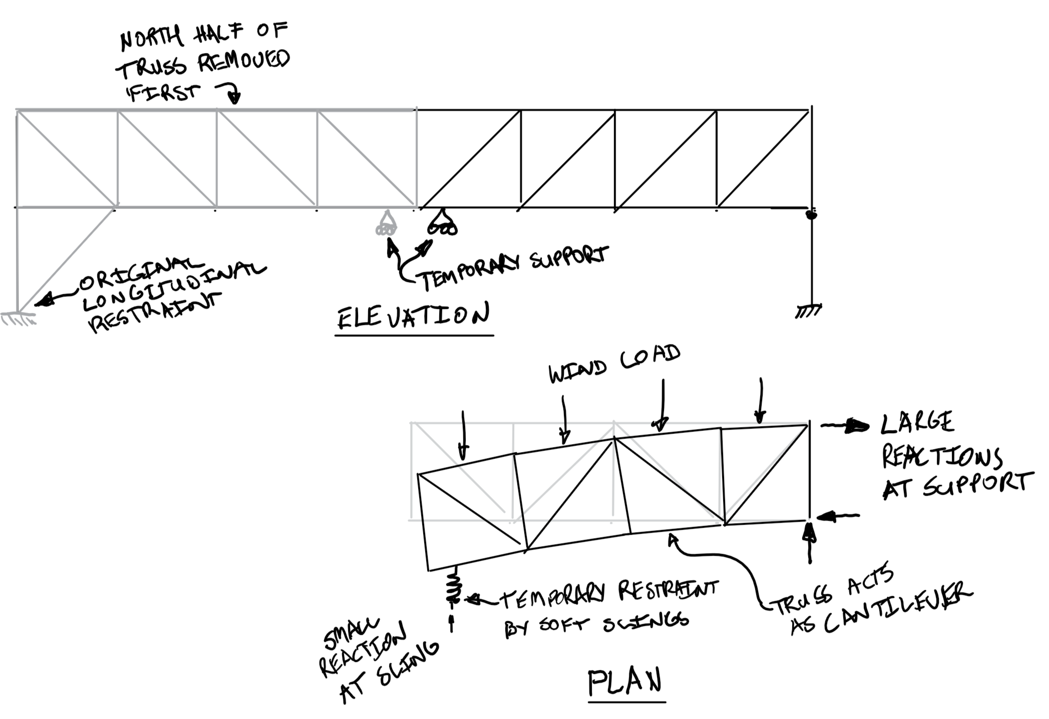
To remove the truss, the plan was to support the centre and cut the gantry in half (the full weight of the conveyor exceeded the crane capacity). At the centre (either side of the cut) the truss was restrained laterally by soft slings (which were modelled as soft spring restraints). The original truss supports were assumed to be infinitely stiff perfect pins. This resulted in the truss acting as a large cantilever under wind loads, with the majority of the wind load going to the original supports and very large longitudinal reactions:
Unfortunately, the lift procedure called for removing the northern half of the truss first (immediately after cutting it in half).This was the location of the original longitudinal restraint. The southern support (for the remaining half truss) was a tall, slender trestle, cantilevered off the berth deck level. This was clearly not designed for longitudinal loads. There was a chance the trestle would be required to withstand at least some wind load - for example if a storm picked up between the lifts, or it was left overnight. A check of its capacity showed that it was significantly overloaded even under very low wind loads.
Being a 3rd party reviewer, I could have just stopped there and recommended that the lift not go ahead. However, the original engineers were comfortable with the arrangement, and checking the trestle would have been a pretty obvious check for them to have done. Thinking about it, I realised that although the trestle was failing because it was a tall, slender trestle - it was a tall slender trestle! Therefore it would have very low stiffness. The standard formula for the deflection of a cantilever is:
\[\Delta = \frac{Pl^3}{3EI}\]This is similar to Hooke’s law - it contains force (\(P\)) and deflection (\(\Delta\)), and the remaining terms can be re-arranged to give an equation for stiffness:
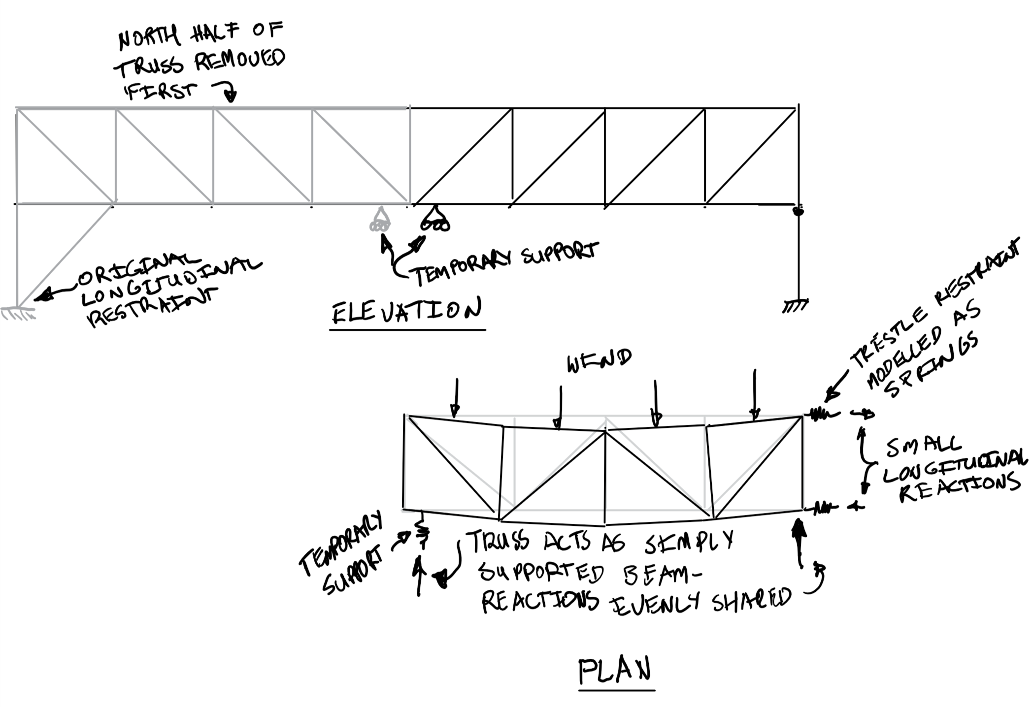
\[k = \frac{3EI}{l^3}\]Using the equation above the stiffness of the trestle was found to be very low. The estimated stiffness was used for spring restraints in the model of the truss. The truss now behaved very close to a simply supported beam under wind load, with load shared approximately equally between the temporary restraint and the trestle. The longitudinal reactions were well within the trestle’s capacity.
The End - For Now…
Hopefully this post has been an interesting look into a real world use of stiffness in structural analysis & design. In my next post I intend to give another example, and think a little about why it took me a few years of my career before I started to understand the importance of stiffness.