Monorails and Flexural-Torsional Buckling
Shortly after writing my previous post on Structural Integrity, I came across a great real world illustration of why engineers who specialise in structural integrity are valuable. It was also interesting because it made me realise that something I had thought was impossible actually is both possible and does occur in real structures.
Let’s Talk About Monorails
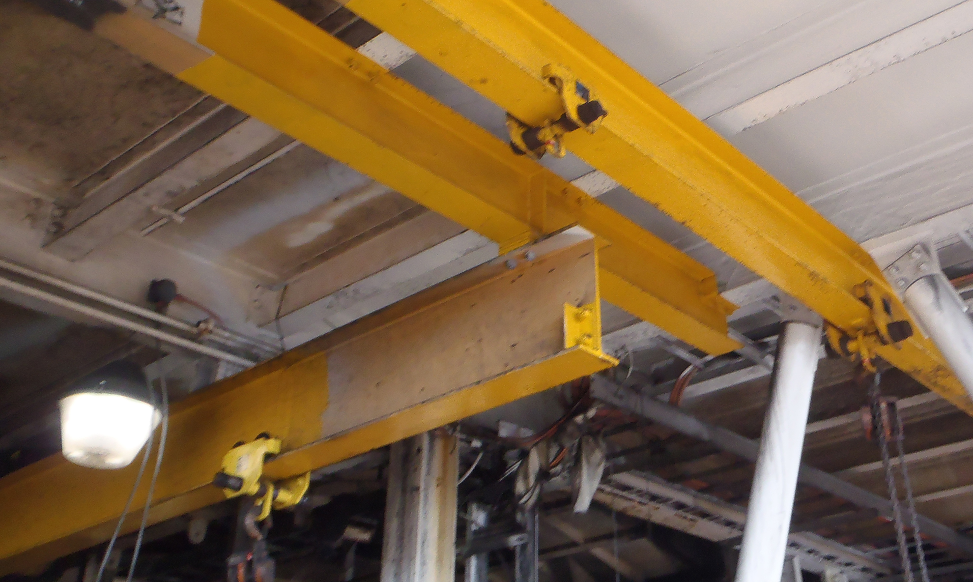
Monorails are everywhere in industrial structures - a typical processing plant that I often work in would have 40-50 scattered around the site. These are necessary because pumps, motors, pipework, conveyor pulleys etc. are too heavy to move by hand and the congested nature of these structures prevents access by crane. The monorails themselves are usually very simple structures consisting of a standard “I” section, with bolted supports in the top flange to allow a free bottom surface for a standard beam trolley to run.
Where The Engineer Comes In
I was at the particular site in question for a different reason, but while walking past a particular monorail the site Structural Integrity Engineer pointed to a monorail and started telling me a story.
While walking through the plant a few months earlier he had come across a couple of workers who had just finished using the monorail. Talking to them in passing, they had mentioned that while they were using the monorail they had noticed that it was deflecting sideways, and not downwards (as they expected).
Monorails are usually used to lift the same object over and over again. Presumably this had been happening every time it had been used since the early 1970s, without anyone ever thinking to wonder about it. However, the site engineer was able to recognise that what the workers were seeing was the onset of Flexural-Torsional buckling of the monorail beam.
Buckling
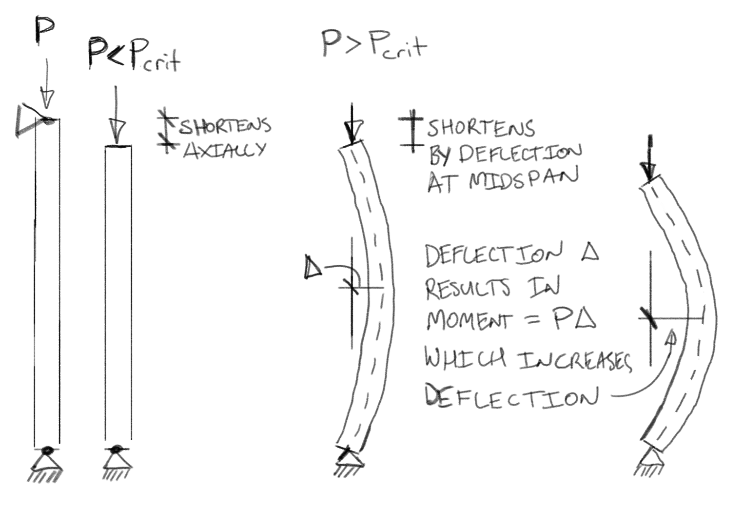
So what is buckling, and why do engineers worry about it? Buckling happens when structures are loaded in compression. They can either get shorter by shrinking a little, or by deflecting sideways (their overall length stays the same but the distance between load and support shortens). Below a load known as the critical buckling load (\(P_{crit}\)) the structure shrinks. Above this load the deflection mode governs.
Unfortunately, the deflection results in the structure being offset from the original compression force. Newton’s law about every force needing an equal and opposite reaction therefore results in a bending moment. The bending moment results in greater deflection, which results in more bending, which results in greater deflection … until your structure falls over.
Buckling failure is dangerous because it can happen suddenly, without warning and without giving time to reduce load or otherwise prevent failure. The list of structures that have failed due to buckling is a long and not-so-illustrious one. For example in Australia the collapse of the West Gate Bridge during its construction which killed 35 workers was largely the result of buckling that occurred due to inadequate design.
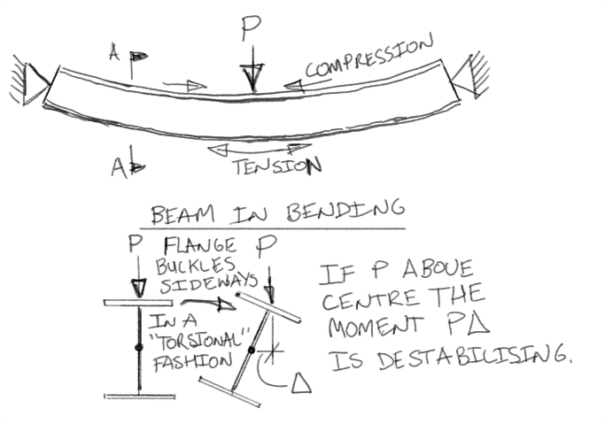
Flexural-torsional buckling occurs because bending places the top flange of a beam into compression. Just like a column in compression, the compression flange of a beam can buckle. The web & tension flange of the beam force the compression flange to buckle sideways, which results in the whole section twisting (hence “torsional” buckling).
This sideways movement of the top flange was what the workers using the monorail had observed. The monorail was effectively at the point of failure at the normal loads that these workers had been placing on it.
It appears that it was simple luck that had prevented workers loading the monorail past the critical buckling load. Without the site engineer present to recognise the issue, it would have continued to have been used, all the while presenting a risk of collapse and injury to workers.
So What Did I Learn?
While an interesting observation in why engineers are necessary, what made this really interesting for me is that I hadn’t thought flexural-torsional buckling was possible for a monorail.
If you have a look at the sketch above, when the load is on the top flange of the beam, the resulting torsional moment \(M=P\Delta\) is de-stabilising and will twist the beam in the same direction that the buckled top flange does, resulting in failure. However, if the load is below the centre of the section the torsion will tend to counteract the effect of the buckling top flange and will try and straighten the section back out. Monorails are almost always loaded on the bottom flange (as was the monorail in question above).
I had naively assumed that this stabilising effect was at least as strong as the tendency of the top flange to buckle, therefore preventing flexural-torsional buckling. However, the story from the site engineer suggested that I was wrong.
Being interested in whether I was wrong or not I built a test model in an FEA package, and lo and behold the monorail beam fails with a very distinctive flexural-torsional buckling of the top flange (the sudden jump to the right approximately ½ way through the gif):
The following figure shows the force-displacement curve for various load heights and a case where buckling has been prevented (forcing failure by yielding of the cross section):
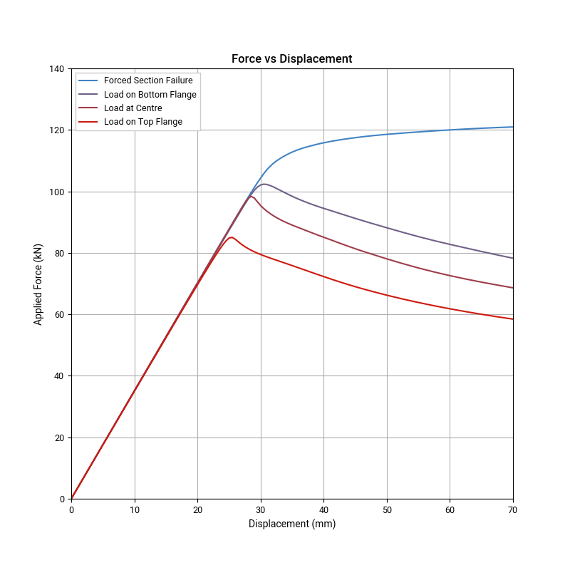
As expected when the load is applied to the top flange there is a reasonably significant decrease in capacity (13% lower than load applied at the centre). When the load is applied at the bottom flange there is only a 4% increase in capacity. This is much smaller than I had expected (I was expected no or very little buckling with close to section capacity). While the exact numbers would vary considerably depending on the load and structure being analysed, at least in this case there is effectively no benefit to the structure from the load being below the centroid of the section.
For those who are not engineers, the sharp nature of the force-displacement curves at the critical buckling load, followed by the sudden drop-off after buckling indicates the dangerous nature of buckling failures. Typically structural loads cannot be reduced in time to prevent the structure following the curve downwards to collapse. In comparison, the section failure mode has a much flatter curve, with significant deflection before final ultimate collapse (which would occur well off the edge of the chart). The high deflection prior to ultimate failure may allow the structure to develop other load paths. It may also give the occupants some warning that failure is about to occur, possibly allowing them to reduce load before ultimate failure occurs.
I expect that for many engineers the fact that flexural-torsional buckling can occur even when loads are below the centroid will not make any difference to their day-to-day practice. AS4100-1998 (the current Australian Standard for steel design) does not provide easy methods to determine how much extra capacity a load below the section centroid provides so typical practice would be to conservatively assume the load is actually at the centroid. However, realising that loads below the centroid do not prevent buckling may be important for those who have to assess existing structures or deal with them on site where signs of buckling may occur.
Summary
The example of a buckling monorail is an interesting real-world example of why engineers are useful, not just in design but also in the day-to-day operations of structures. It’s also a great lesson in not taking things for granted. I don’t know why I had assumed that flexural-torsional buckling is not possible when the load is below the centroid. However I am grateful that I learnt that it is possible through someone else’s near miss, not my own. Hopefully I’ll always be so lucky!